More go with better flow
Optimizing gas turbine performance with precision flow testing
Richard Vogel, Fuel Nozzle & Flow Test Engineer at Sulzer, provides an insight to flow testing and how it benefits gas turbine operators.
Flow testing is used to monitor operating functionality, find changes in a component that have taken place between maintenance intervals and to help determine the lifespan of turbine components. Combining this information with performance and emissions data, it is possible to suggest improvements to individual components that will benefit overall turbine operation.
Due to the complex nature of individual components and the strict tolerances that they operate under, it is important to ensure that variation is minimized. Otherwise, even a small anomaly can contribute to, or develop into, a more serious issue that can affect the service life of combustion and hot gas-path parts. This can result in increased repairs to components, de-rating of the machine, or even being taken offline.
Data for each component’s flow test is collected and recorded. This data is reviewed and shared with the customer. Data is then added to Sulzer’s database for trending, assessment of component condition and to help establish useful life criteria.
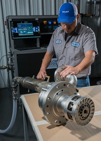
The function and design of various key components need to be verified as part of the periodic maintenance requirements identified by the manufacturers. This is achieved by using highly specialized flow test equipment. Sulzer utilizes pressurized high flow benches, a vacuum suction bench and a liquid flow bench. Sulzer’s flow testing processes consider both the full assembly as well as individual component level or sub-sectional flows.
Optimizing combustion flows
Vacuum flow testing is a great tool for Sulzer and its customers as it replicates the direction of flow that would occur on combustion components while in operation. It is important to verify and adjust the flow rate through combustion liners as part of the overhaul process to ensure temperature uniformity.
The effective flow area of combustion liners, especially louvered liners, may change following the inspection phase of a repair, which involves the removal of thermal barrier coatings and may result in some level of base material also being removed. As a result, this needs to be carefully tested to ensure effective flow areas are maintained, minimizing variation to provide optimum performance and component life once the new barrier coatings have been reapplied.
The primary mixing zone of the combustion liner is where fuel initially enters and is mixed with air. Supplied air is directed through mixing, dilution and louver features of the liners. The position, size and effective flow area of these features affect the fuel/air ratio, flame temperature, flame profile and ultimately the performance and emissions of the turbine. Sulzer specialists have been vacuum flow testing components for nearly 15 years and over that time have built up considerable experience and information that can be applied to today’s equipment.
More recently, Sulzer has incorporated the testing of modern transition pieces that use dilution hole features; much like with combustion liners designed to help control emissions, as well as to help profile flame temperature. As more testing is performed on these components the database of information grows, allowing more informed decisions on the repair, modification, or replacement of liners and transition pieces. This data can also help determine effects on the operation of the turbine relating to sizing of these critical flow control features and orifices.
Resolving power output issues
Flow testing of the first stage nozzle vane segments has proved to be a very important aspect to consider along with the repair and flow test of other components. The first stage nozzle consumes a significant portion of air supplied to the compressor discharge case (CDC). Turbines that are under performing and not achieving their design output can be affected by the issue of over supplying cooling air to the first stage nozzle vane segments.
This simultaneously reduces the required air flow for the process of combustion to take place within the liners, limiting the output performance of a turbine. In such a case the first stage nozzle air flow metering components were worn, allowing more air than needed to be used for cooling of the segments, thereby limiting combustion performance which reduced the machine’s output and efficiency.
Maximizing performance
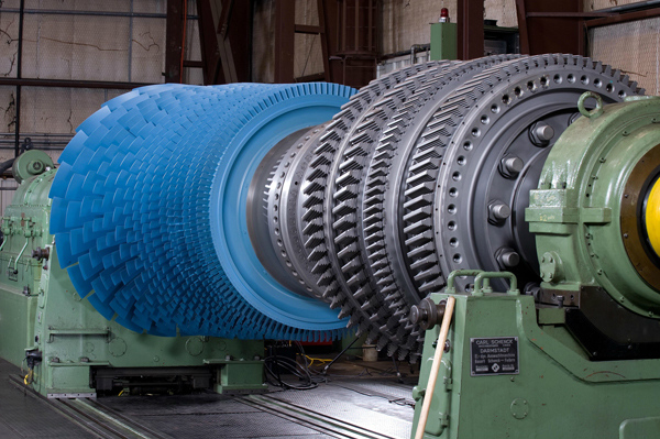
Turbine engines operate in various different environments where small particles can be ingested and accumulate as deposits on a number of the components. This fouling or blockage can significantly affect turbine performance in the case of fuel nozzles by plugging the flow path. It can also lead to physical damage of the machine and to parts in areas where cooling schemes help to keep component materials within acceptable operating parameters, such as with buckets and blades. Sulzer utilizes flow testing, along with its other maintenance procedures, for inspecting these components so as to avoid a dramatic loss in performance or potential damage to components.
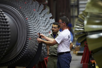
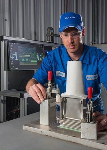
Blades and buckets are tested on the high flow benches to check that none of the cooling passages in the components are blocked. Flow testing also checks for variability within a set of components. The aim is to minimize the deviation from the average results of all the components within the set, making each one deliver an equivalent performance.
It is important that every blade or bucket in a set provide adequate cooling; blocked passages can increase blade temperature resulting in reduced component life, or more critical damage. Evaluating uniformity in sets of component flow data can help pin point parts within a set that may have issues, whether it be blocked cooling or a casting defect from the manufacturing process that can affect flow.
Every part in a set of components being flow tested is analyzed to assess performance based on the effective flow area and / or the mass flow rate through the components. By comparing data from the tests performed when the parts are received to those performed after refurbishment has been completed, it is possible to identify any issues or the need for improvement in performance of the part. Trending this information over time with customers can help develop more informed maintenance schedules and estimates of useful component life.
Assessing liquid flows
Liquid flow testing looks at the liquid fuel, and water injection circuits of the fuel nozzles. Just as with air flow testing, liquid flow testing helps to monitor variability in terms of flow rate through the parts. Liquid flow testing also allows for the visual monitoring of spray patterns, which can indicate component wear or internal blockages.
Liquid circuits need to maintain their spray patterns in order to achieve the correct flame profile and temperature distribution. Wear or internal debris may cause combustor burnout, where the flame can impinge upon the combustion liner or basket wall and cause significant, even irreparable damage to the component.
Creating the right fit
Performing flow tests on the many gas turbine components, Sulzer engineers require specialized fixtures that fit specifically to each part to maintain proper sealing during testing at varying pressures. Proper sealing during testing ensures reliability in test data. Sulzer has honed its skills in fixture development over the many years it has been performing flow tests on the varying geometry on the many models and styles of gas turbine parts it works with.
Sulzer has the capability to quickly design, test and implement the use of custom fixtures for new and varying flow tests as new designs come into use and as the need arises with customers. Sulzer also has the capability to quickly cast custom silicon rubber seals for fitment of the parts to fixtures for testing.
Plugging the leaks
Dynamic leak checks are performed during air flow tests on the high flow benches to help ensure that seals are functioning properly. Sulzer also performs hydrostatic leak testing on various fuel nozzles to ensure the integrity of internal seals and assembly welds of fuel nozzles.
Fuel nozzles exhibiting leaks can cause significant issues with regard to emissions and can affect temperature uniformity and emissions. Fortunately, Sulzer is fully equipped to repair seal leakage issues and in the case of two specific GE gas turbine models, has developed a proprietary seal design that eliminates leakage associated with an original seal design.
Managing a Fleet with Flow Data
Fuel nozzle flow rates need to match those required by the manufacturer’s design specifications in order to achieve the expected output. This criteria may vary from one individual turbine to another, even if the turbines are of the same model type. An evaluation of flow data should be performed and made readily available for inventory spares or sets of fuel nozzles. The use of inventory spares is often the case with larger operators to minimize downtime during outages. These spare fuel nozzles should be clearly identified with a reference that identifies the turbine it originated from and with the most recent specific flow data associated with the fuel nozzles.
Larger organizations that operate multiple turbines in different locations, with an inventory pool of spare parts, could find they have performance issues after swapping out for an inventory set. This, for example, can arise because the fuel nozzles designed for a turbine located close to sea level and local atmospheric conditions will have a different set of specifications to those of the same model, sister-machine located at a differing elevation and local atmospheric conditions. Without a comparison of flow rates, unknowingly swapping these fuel nozzles with varied flow rates, can reduce performance and may even affect the ability to start-up the turbine at all.
A careful review of flow data from the parts being removed from the turbine to those scheduled for installation should be performed to ensure that there are no major differences in component flow data. If minimal differences are present, this analysis can help determine the need for other actions, such as changes to fuel valve settings, operational control adjustments, or even the scheduling for tuning the turbine to ensure minimized downtime and easy startup after an outage has occurred.
Minimizing refurbishment costs
It is essential to test components as soon as they arrive at the service center to establish the baseline data for the component when it was removed from the gas turbine. The ‘as received’ condition data can be logged with any notes about performance or emissions irregularities and help to identify potential corrective actions. In some cases, this test data can identify components that are beyond economic repair and should be replaced, saving the customer any further costs associated with the refurbishment process.
Following the refurbishment process, the components will be tested again to establish the final test figures before they are returned to the customer. Comparing the two data sets will show the changes that have been implemented and can be used to benchmark any changes in performance or emissions when they are reinstalled.
The ultimate aim is to extend the overall lifespan of components, maximizing their operational usefulness without compromising the manufacturer’s standards. By analyzing the data collected it is likely to more accurately predict when components will need refurbishment and when to replace components, based on the trended data.
This is especially true when the data is compared to the history of a machine with known efficient performance and emissions data. While the most accurate data is produced through a long working relationship with a customer, it is also possible to use data from similar gas turbines to offer a very educated estimate for equipment that has not previously been flow tested or refurbished by Sulzer.
Experience counts for everything
Sulzer has always worked very closely with its customers and it is vital that all of the information gained from a sequence of flow tests be shared and discussed openly to ensure the most appropriate solution is delivered for each gas turbine. In addition, each data set is analyzed and added to historical information to help diagnose issues in the future. In this aspect, experience counts for everything when it comes to assessing components and their continued operation before being replaced.
Ultimately, flow testing aims to remove anomalies from a system; minimizing variation and deliver a more efficient machine. Minimizing temperature spread and vibration reduces wear to components which reduces repair and maintenance costs. All this improves performance and the bottom line.
